Announced
Instant-IO-Link Solution for Remote Monitoring your Sensor Data
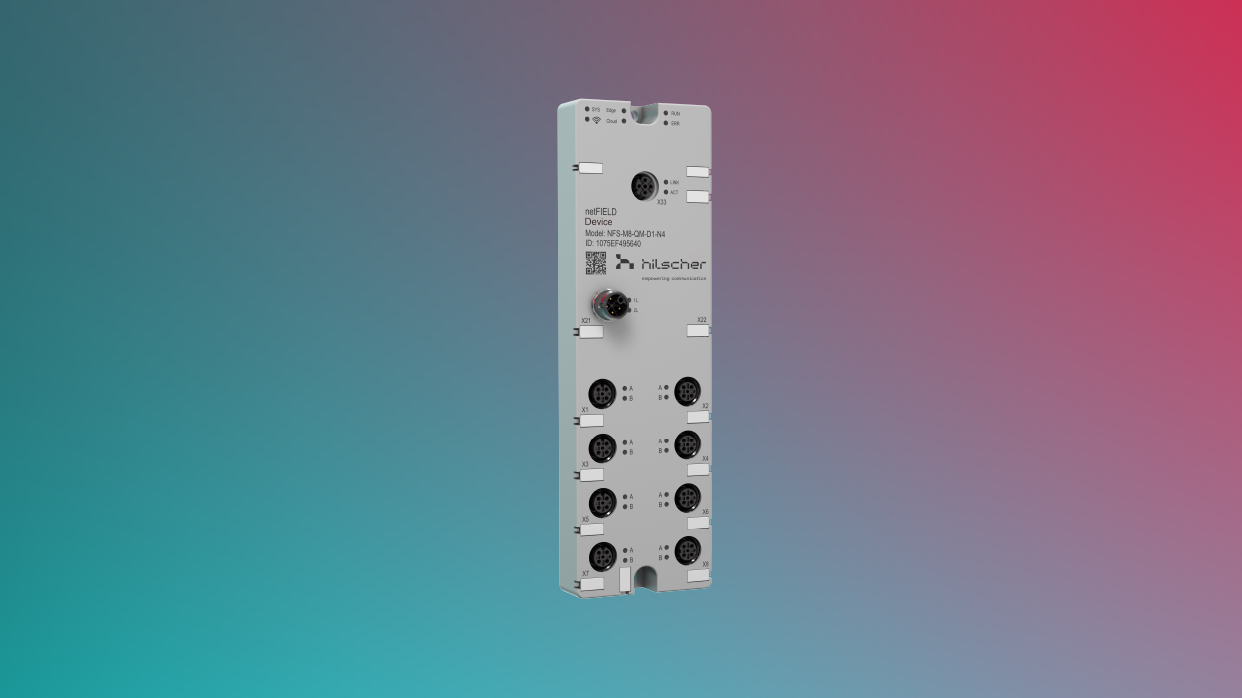
sensorEDGE is Hilscher’s solution for fast remote monitoring your machines. Equipped with two netIOL chips – an IO-Link master controller developed by Hilscher – as well as a cloud uplink, the sensor box enables data monitoring and analyzing of up to eight IO-Link sensors simultaneously.
sensorEDGE simply needs a power supply and an internet connection. A complex setup of a PLC or fieldbus system is not required.
As soon as sensors are plugged in and are autonomously configured via the online IODD file database, the sensor-box transmits data into the cloud at a rate of a second. The data can either be visualized immediately in the corresponding cloud web frontend or streamed into any third-party application utilizing the integrated API.
sensorEDGE is the ideal solution for retrofitting existing plants which had been managed and operated locally but have never been remotely monitored. The sensor-box is compatible with all IO-Link-sensors that operate in accordance with the IEC 61131-9 protocol standard, simplifying the implementation of sensorEDGE enormously. The IP67-rated casing is able to withstand harshest environments and allows for a cabinet-free installation close to your machines.
Category | Parameter | Value |
---|---|---|
General | Part number | 1915.230 |
Functions | 8-port IO-Link Master (Class A) Edge Device with sensorEDGE Cloud connectivity | |
Power supply | Supply voltage | +24 V DC, –25%/+30% (18 V DC … 31.2 V DC)
Note: Voltages above 34 V may cause permanent damage to the device. Voltages below approx. 10 V will cause a shutdown of the device. Note: The sensorEDGE does not need or use auxiliary supply voltage (U2L), even though the pins for the 2L auxiliary load circuit are implemented on the device. The 1L and 2L load circuits are galvanically isolated from each other. |
Under-voltage warning | U1L < 18 V: 1L LED shows steady red
U1L > 17.7 V: 1L LED returns to steady green | |
Over-voltage warning | U1L > 30 V: 1L LED blinking red (4 Hz)
U1L < 29.7 V: 1L LED returns to steady green | |
Current consumption (typical) | 150 – 160 mA (at 24 V DC) | |
Maximum current at supply connector | 16 A with airflow of ~ 0.5 m/s. 3.36 A without airflow Note: Always protect the power supply with a circuit breaker or fuse. For this purpose, use a 24 V DC / max. 16 A fuse or circuit breaker with type B trip characteristics. | |
Reverse voltage protection | Yes | |
Mains buffering (power failure bridging) | 10 ms (at 24 V) | |
Connector | M12 L-coded, male, 5-pin (4 + FE) Recommended tightening torque of locking nut: 0.4 – 0.6 Nm | |
Mechanics and housing | Dimension (L x W x H) | 200 mm x 60 mm x 30 mm |
Weight | 420 g | |
Housing material | Glass fiber reinforced plastic (PBT) according to UL 94-V0 | |
Housing color | RAL 7035 (“light gray”) | |
Degree of protection | IP67 (EN 60529) | |
Protection class | III (EN 61140) | |
Mounting type | To be attached to carrier with two M4 screws. Recommended tightening torque: 0.8 Nm | |
Admissible ambient conditions | Ambient temperature for operation | –25 °C … +60 °C at maximum current consumption per IO-Link port of 400 mA without airflow.
–25 °C … +60 °C at maximum current consumption per IO-Link port of 1800 mA with airflow of ~ 0.5 m/s. |
Ambient temperature for storage | –40 °C … +85 °C | |
Max. temperature change | 3 K / min | |
Relative humidity (operation) | 5 % … 95 % | |
Pollution degree | 3 (EN 60664-1) | |
Altitude | 0 ... 2000 m | |
Overvoltage category | II (EN 60664-1) | |
Electromagnetic compatibility (EMC) | Radio Interference Field Strength Emission | DIN EN 55016-2-3 / BS EN 55016-2-3 |
Radiated Field Immunity | DIN EN 61000-4-3 / BS EN 61000-4-3 | |
Conducted Disturbances Immunity | DIN EN 61000-4-6 / BS EN 61000-4-6 | |
Radio Interference Voltage Emission | DIN EN 55016-2-1 / BS EN 55016-2-1 | |
ESD contact discharge | DIN EN 61000-4-2 / BS EN 61000-4-2 4 kV | |
Burst | DIN EN 61000-4-4 / BS EN 61000-4-4 | |
Surge | DIN EN 61000-4-5 / BS EN 61000-4-5 | |
Mechanical tests | Vibration sinusoidal | DIN EN 60068-2-6:2008 (including monitoring for contact breaks according to DIN EN 60512-2-5:2004) |
Shock | DIN EN 60068-2-27:2010 (including monitoring for contact breaks according to DIN EN 60512-2-5:2004) | |
Free fall | DIN EN 60068-2-31:2009 | |
Approvals | UL | In preparation |
Conformity declarations | CE | Yes |
UKCA | Yes | |
RoHS | Yes | |
REACH | Yes | |
Ethernet LAN interface | Type | 10/100 MBit/s Ethernet port (eth0) |
Connector | M12, D-coded, female, 4-pin.
Recommended tightening torque of locking screw: 0.4 – 0.6 Nm | |
IO-Link | Type | IO-Link Master, Class A, 8 ports |
Connector | 8 x M12 A-coded, female, 5-pole
Recommended tightening torque of locking screw: 0.4 – 0.6 Nm Maximum cable length: 20 m. | |
LED indicators | SYS (green/yellow) | “System” status LED of the communication controller |
Currently without function (reserved for future use) | ||
EDG (red/green) | “Edge” LED indicating configuration and operating states of the IO-Link sensors | |
CLD (red/green) | “Cloud” LED indicating connectivity with the Internet/cloud | |
RUN (red/green) | Currently without function (reserved for future use) | |
ERR (red/green) | Currently without function (reserved for future use) | |
LINK (green) | Ethernet Link status | |
ACT (yellow) | Ethernet Activity status | |
1L (red/green) | Indicates supply voltage status | |
2L (green) | Indicates supply voltage status of second load circuit (U2L).
Note: The sensorEDGE does not need or use auxiliary supply voltage (U2L), even though the 2L LED and the pins for the 2L auxiliary load circuit are implemented on the device. | |
8 x A (red/green/yellow) | Status of the IO-Link port
(Note: Yellow is produced by switching red and green duo LED on at the same time) | |
8 x B (red/green/yellow) | Not used |
Category | Parameter | Value |
---|---|---|
IO-Link Master (Class A) | Specification | V1.1.2 |
Port mode | IO-Link autoconfig | |
Min. cycle time | 400 µs | |
Sensor supply | Output voltage | 24 V DC, 1L-powered |
Current | Maximum current consumption per IO-Link port without airflow: 400 mA.
Maximum current consumption per IO-Link port with airflow of ~ 0.5 m/s: 1800 mA. | |
Circuit | High-side driver, no back current protection from 1L+ output. |
Product name | Part number | Brief description |
---|---|---|
NFS-M8-QM-D2-N16 | 1915.230 | sensorEDGE - Cloud based instant IO-Link data provisioning solution |
The sensorEDGE Portal provides functions to update the software of the sensorEDGE device.
Find all our current Media to Industry 4.0 / Industrial Internet at our Media Archive.