 |
Hilscher netX microcontroller driver
V0.0.5.0
Documentation of the netX driver package
|
|
Hilscher netX microcontroller driver
V0.0.5.0
Documentation of the netX driver package
|
mled_ctrl_app (mled_ctrl_app) More...
#include <netx90_app.h>
Data Fields | |
| union { | |
| __IOM uint32_t mled_ctrl_app_cfg | |
| struct { | |
| __IOM uint32_t enable: 1 | |
| __IOM uint32_t prescale_counter_max: 10 | |
| __IOM uint32_t blink_counter_max: 9 | |
| __IOM uint32_t bf_align0: 12 | |
| } mled_ctrl_app_cfg_b | |
| }; | |
| union { | |
| __IOM uint32_t mled_ctrl_app_output_sel [16] | |
| struct { | |
| __IOM uint32_t inv: 1 | |
| __IOM uint32_t sel: 2 | |
| __IOM uint32_t bf_align0: 29 | |
| } mled_ctrl_app_output_sel_b [16] | |
| }; | |
| union { | |
| __IOM uint32_t mled_ctrl_app_output_on_time [16] | |
| struct { | |
| __IOM uint32_t val: 8 | |
| __IOM uint32_t bf_align0: 24 | |
| } mled_ctrl_app_output_on_time_b [16] | |
| }; | |
| union { | |
| __IOM uint32_t mled_ctrl_app_line0 | |
| struct { | |
| __IOM uint32_t val: 16 | |
| __IOM uint32_t bf_align0: 16 | |
| } mled_ctrl_app_line0_b | |
| }; | |
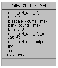
mled_ctrl_app (mled_ctrl_app)
Definition at line 24516 of file netx90_app.h.
| union { ... } |
< (@ 0xFF801300) mled_ctrl_app Structure
| union { ... } |
| union { ... } |
| union { ... } |
| __IOM uint32_t mled_ctrl_app_Type::bf_align0 |
[31..20] bitField alignment value for aeabi compatibility
[31..3] bitField alignment value for aeabi compatibility
[31..8] bitField alignment value for aeabi compatibility
[31..16] bitField alignment value for aeabi compatibility
Definition at line 24547 of file netx90_app.h.
| __IOM uint32_t mled_ctrl_app_Type::blink_counter_max |
[19..11] Maximum value the blink counter will count to. The blink counter determines the blink frequency: f_blink = 50 Hz / (blink_counter_max + 1) blink_counter_max = (50 Hz / f_blink) - 1. The range of the blink frequency is therefore within ~0.1 Hz and 50 Hz.
Definition at line 24542 of file netx90_app.h.
| __IOM uint32_t mled_ctrl_app_Type::enable |
[0..0] Writing a '1' to this bit will enable the MLED_CTRL_APP module. When disabled, all counters will be stopped to save power and outputs will be switched to high-z state.
Definition at line 24533 of file netx90_app.h.
| __IOM uint32_t mled_ctrl_app_Type::inv |
[0..0] Invert input signal.
Definition at line 24555 of file netx90_app.h.
| __IOM uint32_t mled_ctrl_app_Type::mled_ctrl_app_cfg |
(@ 0x00000000) Global configuration register. This register controls global configuration options for all Multi-LED outputs. Description of Multi-LED control module operation: a) Time-multiplexed PWM mode: Each output drives two LEDs: Low-side and high-side LED. Three states of the output pin are possible: High (i.e. the low-side LED is on), low (i.e. the high-side LED is on), or high-z (i.e. both LEDs are off). The PWM period, determined by bit field prescale_counter_max, is the same for all outputs. Th
Definition at line 24519 of file netx90_app.h.
| struct { ... } mled_ctrl_app_Type::mled_ctrl_app_cfg_b |
| __IOM uint32_t mled_ctrl_app_Type::mled_ctrl_app_line0 |
(@ 0x00000084) Line register. The line register allows changing all LEDs (configured to line mode) at once to a new value. Note: The change will take effect at the start of the next PWM period (when the output operates in time-multiplexed PWM mode). In pass-through mode, the change will take effect immediately.
Definition at line 24579 of file netx90_app.h.
| struct { ... } mled_ctrl_app_Type::mled_ctrl_app_line0_b |
| __IOM uint32_t mled_ctrl_app_Type::mled_ctrl_app_output_on_time[16] |
(@ 0x00000044) Output 0 phase 0 (high-side LED) switch-on time.
Definition at line 24565 of file netx90_app.h.
| struct { ... } mled_ctrl_app_Type::mled_ctrl_app_output_on_time_b[16] |
| __IOM uint32_t mled_ctrl_app_Type::mled_ctrl_app_output_sel[16] |
(@ 0x00000004) Output 0 phase 0 (high-side LED) configuration.
Definition at line 24552 of file netx90_app.h.
| struct { ... } mled_ctrl_app_Type::mled_ctrl_app_output_sel_b[16] |
| __IOM uint32_t mled_ctrl_app_Type::prescale_counter_max |
[10..1] Maximum value the prescale counter will count to. The prescale counter determines the PWM frequency of all outputs: f_pwm = f_clk / (512 * (prescale_counter_max + 1)) prescale_counter_max = (f_clk / (512 * f_pwm)) - 1 with f_clk = 100 MHz (netX system frequency). The range of the PWM frequency is therefore within ~191 Hz and ~195 kHz.
Definition at line 24536 of file netx90_app.h.
| __IOM uint32_t mled_ctrl_app_Type::sel |
[2..1] Selection of the signal connected to this output. { | Value Input 0 always off 1 line register 2 MLED_CTRL blink 3 pass-through (for phase 0 registers) / reserved (for phase 1 registers) }
Definition at line 24556 of file netx90_app.h.
| __IOM uint32_t mled_ctrl_app_Type::val |
[7..0] Switch-on time of this LED. This value determines the period during which the output is active. The value helps achieve a consistent brightness of different LED types. Dimming individual LEDs is also possible. Possible values are 0 (off) to 255 (on for the full phase minus one PWM tick).
[15..0] MLED output values 15..0 when line mode is selected in the corresponding 'sel' register.
Definition at line 24568 of file netx90_app.h.
 1.8.11