 |
Hilscher netX microcontroller driver
V0.0.5.0
Documentation of the netX driver package
|
|
Hilscher netX microcontroller driver
V0.0.5.0
Documentation of the netX driver package
|
madc (madc) More...
#include <netx90_app.h>
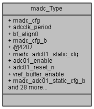
madc (madc)
Definition at line 17265 of file netx90_app.h.
| union { ... } |
< (@ 0xFF4017E0) madc Structure
| union { ... } |
| union { ... } |
| union { ... } |
| union { ... } |
| union { ... } |
| union { ... } |
| __IOM uint32_t madc_Type::adc01_enable |
[0..0] Power-down mode of ADC0 and ADC1: 1: Enable ADC (Power up) 0: Disable ADC (Power-down)
Definition at line 17288 of file netx90_app.h.
| __IOM uint32_t madc_Type::adc01_reset_n |
[1..1] Low active reset of ADC0 and ADC1 and their state machines: 1: Soft-Reset is inactive. 0: Soft-Reset is active. A reset can be applied at any time during a currently running conversion cycle. There are no constraints on reset length.
Definition at line 17290 of file netx90_app.h.
| __IOM uint32_t madc_Type::adc23_enable |
[0..0] Power-down mode of ADC2 and ADC3: 1: Enable ADC (Power up) 0: Disable ADC (Power-down)
Definition at line 17313 of file netx90_app.h.
| __IOM uint32_t madc_Type::adc23_reset_n |
[1..1] Low active reset of ADC2 and ADC3 and their state machines: 1: Soft-Reset is inactive. 0: Soft-Reset is active. A reset can be applied at any time during a currently running conversion cycle. There are no constraints on reset length.
Definition at line 17315 of file netx90_app.h.
| __IOM uint32_t madc_Type::adcclk_period |
[7..0] Max value of global ADC synchronization counter: ADCs running at same adcclk might interfere. Therefore the ADCs should be able to run in different clk-phases. Adcclk generation will be done within the ADC sequencers. This value is used to configure a global counter for clock phase reference. It's value should be the same or an natural numbered multiple of the value configured in ADC sequencers.
Definition at line 17271 of file netx90_app.h.
| __IOM uint32_t madc_Type::bf_align0 |
[31..8] bitField alignment value for aeabi compatibility
[31..3] bitField alignment value for aeabi compatibility
[31..2] bitField alignment value for aeabi compatibility
[31..4] bitField alignment value for aeabi compatibility
Definition at line 17278 of file netx90_app.h.
| __IOM uint32_t madc_Type::dt0 |
[15..0] delay for DTEVT[0]
Definition at line 17354 of file netx90_app.h.
| __IOM uint32_t madc_Type::dt1 |
[31..16] delay for DTEVT[1]
Definition at line 17355 of file netx90_app.h.
| __IOM uint32_t madc_Type::dt2 |
[15..0] delay for DTEVT[2]
Definition at line 17367 of file netx90_app.h.
| __IOM uint32_t madc_Type::dt3 |
[31..16] delay for DTEVT[3]
Definition at line 17368 of file netx90_app.h.
| __IOM uint32_t madc_Type::dt4 |
[15..0] delay for DTEVT[4]
Definition at line 17380 of file netx90_app.h.
| __IOM uint32_t madc_Type::dt5 |
[31..16] delay for DTEVT[5]
Definition at line 17381 of file netx90_app.h.
| __IOM uint32_t madc_Type::madc_adc01_static_cfg |
(@ 0x00000004) Static configuration signals (D2A) to the MAZ IP containing the analog modules ADC0 to ADC3.
Definition at line 17283 of file netx90_app.h.
| struct { ... } madc_Type::madc_adc01_static_cfg_b |
| __IOM uint32_t madc_Type::madc_adc23_static_cfg |
(@ 0x00000008) Static configuration signals (D2A) to the MAZ IP containing the analog modules ADC0 to ADC3.
Definition at line 17308 of file netx90_app.h.
| struct { ... } madc_Type::madc_adc23_static_cfg_b |
| __IOM uint32_t madc_Type::madc_cfg |
(@ 0x00000000) Config bits for the MADC common module.
Definition at line 17268 of file netx90_app.h.
| struct { ... } madc_Type::madc_cfg_b |
| __IOM uint32_t madc_Type::madc_deadtime01_delay |
(@ 0x00000010) Dead time delay: Delay in steps of system clock (10ns) between Dead Time EVenT from PWM module and trigger. In case of 2nd DTEVT within delay time, the second DTEVT will be lost.
Definition at line 17347 of file netx90_app.h.
| struct { ... } madc_Type::madc_deadtime01_delay_b |
| __IOM uint32_t madc_Type::madc_deadtime23_delay |
(@ 0x00000014) Dead time delay: Delay in steps of system clock (10ns) between Dead Time Event from PWM module and trigger. In case of 2nd Dead Time Event within delay time, the second DTEVT will be lost.
Definition at line 17360 of file netx90_app.h.
| struct { ... } madc_Type::madc_deadtime23_delay_b |
| __IOM uint32_t madc_Type::madc_deadtime45_delay |
(@ 0x00000018) Dead time delay: Delay in steps of system clock (10ns) between Dead Time Event from PWM module and trigger. In case of 2nd Dead Time Event within delay time, the second DTEVT will be lost.
Definition at line 17373 of file netx90_app.h.
| struct { ... } madc_Type::madc_deadtime45_delay_b |
| __IOM uint32_t madc_Type::madc_start |
(@ 0x0000000C) ADC start register: This register allows to start all ADCs in parallel. All further configuration is done within the ADC sequencers. Also ADCs can be started from their sequencers address range. This register is writable but can also be changed by hardware (reset).
Definition at line 17324 of file netx90_app.h.
| struct { ... } madc_Type::madc_start_b |
| __IOM uint32_t madc_Type::start_adc0 |
[0..0] Start ADC0: Setting this bit to 1 starts ADC control state machine for ADC0. It will reset automatically after sampling phase. If it is reset, it can be set for next conversion. If start_adc0 and start_adc1 are set, the next conversion will be started after both ADCs are finished. Otherwise the next conversion will start directly after current conversion of ADC0 is finished.
Definition at line 17332 of file netx90_app.h.
| __IOM uint32_t madc_Type::start_adc1 |
[1..1] Start ADC1:
Definition at line 17339 of file netx90_app.h.
| __IOM uint32_t madc_Type::start_adc2 |
[2..2] Start ADC2:
Definition at line 17340 of file netx90_app.h.
| __IOM uint32_t madc_Type::start_adc3 |
[3..3] Start ADC3:
Definition at line 17341 of file netx90_app.h.
| __IOM uint32_t madc_Type::vref_buffer_enable |
[2..2] Output Enable for internal Vref buffer Three modes are supported for generation of ADC Reference voltage (vref): { | 1. Use VDD3 (3,3V supply of analog core) as reference: This mode might be inaccurate due to jitter on VDD3. To enable this mode set static_cfg-vref=1 inside the related MADC_SEQ module. The vref_buffer_enable need not be set, if all ADCs use VDD3. 2. Use internal 2.6V reference: This mode requires an external capacitor at pin ADC_VREF, which will be driven to 2.6V from internal vref_buffer.
Definition at line 17294 of file netx90_app.h.
 1.8.11