 |
Hilscher netX microcontroller driver
V0.0.5.0
Documentation of the netX driver package
|
|
Hilscher netX microcontroller driver
V0.0.5.0
Documentation of the netX driver package
|
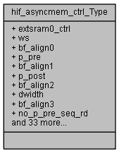
hif_asyncmem_ctrl (hif_asyncmem_ctrl) More...
#include <netx90_app.h>
Data Fields | |
| union { | |
| __IOM uint32_t extsram0_ctrl | |
| struct { | |
| __IOM uint32_t ws: 6 | |
| __IOM uint32_t bf_align0: 2 | |
| __IOM uint32_t p_pre: 2 | |
| __IOM uint32_t bf_align1: 6 | |
| __IOM uint32_t p_post: 2 | |
| __IOM uint32_t bf_align2: 6 | |
| __IOM uint32_t dwidth: 2 | |
| __IOM uint32_t bf_align3: 2 | |
| __IOM uint32_t no_p_pre_seq_rd: 1 | |
| __IOM uint32_t no_p_post_seq_rd: 1 | |
| __IOM uint32_t static_cs: 1 | |
| __IOM uint32_t ready_en: 1 | |
| } extsram0_ctrl_b | |
| }; | |
| union { | |
| __IOM uint32_t extsram1_ctrl | |
| struct { | |
| __IOM uint32_t ws: 6 | |
| __IOM uint32_t bf_align0: 2 | |
| __IOM uint32_t p_pre: 2 | |
| __IOM uint32_t bf_align1: 6 | |
| __IOM uint32_t p_post: 2 | |
| __IOM uint32_t bf_align2: 6 | |
| __IOM uint32_t dwidth: 2 | |
| __IOM uint32_t bf_align3: 2 | |
| __IOM uint32_t no_p_pre_seq_rd: 1 | |
| __IOM uint32_t no_p_post_seq_rd: 1 | |
| __IOM uint32_t static_cs: 1 | |
| __IOM uint32_t ready_en: 1 | |
| } extsram1_ctrl_b | |
| }; | |
| union { | |
| __IOM uint32_t extsram2_ctrl | |
| struct { | |
| __IOM uint32_t ws: 6 | |
| __IOM uint32_t bf_align0: 2 | |
| __IOM uint32_t p_pre: 2 | |
| __IOM uint32_t bf_align1: 6 | |
| __IOM uint32_t p_post: 2 | |
| __IOM uint32_t bf_align2: 6 | |
| __IOM uint32_t dwidth: 2 | |
| __IOM uint32_t bf_align3: 2 | |
| __IOM uint32_t no_p_pre_seq_rd: 1 | |
| __IOM uint32_t no_p_post_seq_rd: 1 | |
| __IOM uint32_t static_cs: 1 | |
| __IOM uint32_t ready_en: 1 | |
| } extsram2_ctrl_b | |
| }; | |
| union { | |
| __IOM uint32_t extsram3_ctrl | |
| struct { | |
| __IOM uint32_t ws: 6 | |
| __IOM uint32_t bf_align0: 2 | |
| __IOM uint32_t p_pre: 2 | |
| __IOM uint32_t bf_align1: 6 | |
| __IOM uint32_t p_post: 2 | |
| __IOM uint32_t bf_align2: 6 | |
| __IOM uint32_t dwidth: 2 | |
| __IOM uint32_t bf_align3: 2 | |
| __IOM uint32_t no_p_pre_seq_rd: 1 | |
| __IOM uint32_t no_p_post_seq_rd: 1 | |
| __IOM uint32_t static_cs: 1 | |
| __IOM uint32_t ready_en: 1 | |
| } extsram3_ctrl_b | |
| }; | |
| union { | |
| __IOM uint32_t ext_cs0_apm_ctrl | |
| struct { | |
| __IOM uint32_t ws_apm: 4 | |
| __IOM uint32_t bf_align0: 4 | |
| __IOM uint32_t apm_cfg: 3 | |
| __IOM uint32_t bf_align1: 21 | |
| } ext_cs0_apm_ctrl_b | |
| }; | |
| __IM uint32_t | RESERVED [3] |
| union { | |
| __IOM uint32_t ext_rdy_cfg | |
| struct { | |
| __IOM uint32_t rdy_act_level: 1 | |
| __IOM uint32_t bf_align0: 3 | |
| __IOM uint32_t rdy_filter: 2 | |
| __IOM uint32_t bf_align1: 2 | |
| __IOM uint32_t rdy_to_irq_en: 1 | |
| __IOM uint32_t bf_align2: 2 | |
| __IOM uint32_t rdy_to_dis: 1 | |
| __IOM uint32_t bf_align3: 20 | |
| } ext_rdy_cfg_b | |
| }; | |
| union { | |
| __IOM uint32_t ext_rdy_status | |
| struct { | |
| __IOM uint32_t rdy_to_err_adr: 27 | |
| __IOM uint32_t bf_align0: 1 | |
| __IOM uint32_t rdy_to_err_cs: 2 | |
| __IOM uint32_t bf_align1: 1 | |
| __IOM uint32_t rdy_to_err: 1 | |
| } ext_rdy_status_b | |
| }; | |
hif_asyncmem_ctrl (hif_asyncmem_ctrl)
Definition at line 15268 of file netx90_app.h.
| union { ... } |
< (@ 0xFF401500) hif_asyncmem_ctrl Structure
| union { ... } |
| union { ... } |
| union { ... } |
| union { ... } |
| union { ... } |
| union { ... } |
| __IOM uint32_t hif_asyncmem_ctrl_Type::apm_cfg |
[10..8] APM configuration. 000 : read bursts are disabled 001 : 1 D-word (4 byte) address boundary for APM 010 : 2 D-word (8 byte) address boundary for APM 011 : 4 D-word (16 byte) address boundary for APM 100 : 8 D-word (32 byte) address boundary for APM 101 : 16 D-word (64 byte) address boundary for APM 110 : 32 D-word (128 byte) address boundary for APM all other settings are reserved. APM burst length programming is related to system address boundaries. For correct programming device data width and page si
Definition at line 15455 of file netx90_app.h.
| __IOM uint32_t hif_asyncmem_ctrl_Type::bf_align0 |
[7..6] bitField alignment value for aeabi compatibility
[7..4] bitField alignment value for aeabi compatibility
[3..1] bitField alignment value for aeabi compatibility
[27..27] bitField alignment value for aeabi compatibility
Definition at line 15292 of file netx90_app.h.
| __IOM uint32_t hif_asyncmem_ctrl_Type::bf_align1 |
[15..10] bitField alignment value for aeabi compatibility
[31..11] bitField alignment value for aeabi compatibility
[7..6] bitField alignment value for aeabi compatibility
[30..30] bitField alignment value for aeabi compatibility
Definition at line 15302 of file netx90_app.h.
| __IOM uint32_t hif_asyncmem_ctrl_Type::bf_align2 |
[23..18] bitField alignment value for aeabi compatibility
[10..9] bitField alignment value for aeabi compatibility
Definition at line 15312 of file netx90_app.h.
| __IOM uint32_t hif_asyncmem_ctrl_Type::bf_align3 |
[27..26] bitField alignment value for aeabi compatibility
[31..12] bitField alignment value for aeabi compatibility
Definition at line 15322 of file netx90_app.h.
| __IOM uint32_t hif_asyncmem_ctrl_Type::dwidth |
[25..24] Data bus width of ExtMem0 area. 00 : 8bit memory device connected to this chip-select address area. 01 : 16bit memory device connected to this chip-select address area. 10 : reserved. 11 : memory is disabled, related chip-select signal can be used for other purpose (e.g. as PIO). Note: Chip-selects are disabled by default. However it could be possible that they are enabled during netX boot phase to search for boot device. View bootloader information for this. Note: When chip-select is disabled related net
[25..24] Data bus width of ExtMem1 area. Note: This chip-select is disabled by default and may be shared with other functions. View memory interface multiplex options for more information.
[25..24] Data bus width of ExtMem2 area. Note: This chip-select is disabled by default and may be shared with other functions. View memory interface multiplex options for more information.
[25..24] Data bus width of ExtMem3 area. Note: This chip-select is disabled by default and may be shared with other functions. View memory interface multiplex options for more information.
Definition at line 15313 of file netx90_app.h.
| __IOM uint32_t hif_asyncmem_ctrl_Type::ext_cs0_apm_ctrl |
(@ 0x00000010) Asynchronous Page Mode (APM) Control Register for ExtMem0 chip-select area. Only ExtMem0 chip-select area supports fast Asynchronous-Page-Mode (APM) Access. Note: This register can be protected by the register MODULE_FIREWALL_CTRL.firewall_cf _hifmemctrl.
Definition at line 15436 of file netx90_app.h.
| struct { ... } hif_asyncmem_ctrl_Type::ext_cs0_apm_ctrl_b |
| __IOM uint32_t hif_asyncmem_ctrl_Type::ext_rdy_cfg |
(@ 0x00000020) External Memory Ready Control Register. Note: Timeout is generated if ready usage is enabled by the extsramX_ctrl registers and is not asserted to active state within 10us. Note: This register can be protected by the register MODULE_FIREWALL_CTRL.firewall_cfg_hifmemctrl.
Definition at line 15470 of file netx90_app.h.
| struct { ... } hif_asyncmem_ctrl_Type::ext_rdy_cfg_b |
| __IOM uint32_t hif_asyncmem_ctrl_Type::ext_rdy_status |
(@ 0x00000024) External Memory Ready Status Register. Note: Timeout is generated if ready usage is enabled by the extsramX_ctrl registers and is not asserted to active state within 10us. Note: This register can be protected by the register MODULE_FIREWALL_CTRL.firewall_cfg_hifmemctrl.
Definition at line 15512 of file netx90_app.h.
| struct { ... } hif_asyncmem_ctrl_Type::ext_rdy_status_b |
| __IOM uint32_t hif_asyncmem_ctrl_Type::extsram0_ctrl |
(@ 0x00000000) Control Register for external bus interface and wait-states for chip-select 0 area. External addresses always be byte addresses. For additional byte-enables/DQM signals view netX pinout documentation. For all wait state configuration 1 cycle is 1 netx system clock cycle, i.e. 10ns for netX running on 100MHz at normal operation. Note: Pause and data width configuration is compatible to netx500/100 and netx50. Note: This register can be protected by the register MODULE_FIREWALL_CTRL.fire all_c
Definition at line 15271 of file netx90_app.h.
| struct { ... } hif_asyncmem_ctrl_Type::extsram0_ctrl_b |
| __IOM uint32_t hif_asyncmem_ctrl_Type::extsram1_ctrl |
(@ 0x00000004) Control Register for external bus interface and wait-states for chip-select 1 area. For detailed register description view extsram0_ctrl register. Note: This register can be protected by the register MODULE_FIREWALL_CTRL.firewall_cfg_hifmemct l.
Definition at line 15358 of file netx90_app.h.
| struct { ... } hif_asyncmem_ctrl_Type::extsram1_ctrl_b |
| __IOM uint32_t hif_asyncmem_ctrl_Type::extsram2_ctrl |
(@ 0x00000008) Control Register for external bus interface and wait-states for chip-select 2 area. For detailed register description view extsram0_ctrl register. Note: This register can be protected by the register MODULE_FIREWALL_CTRL.firewall_cfg_hifmemct l.
Definition at line 15384 of file netx90_app.h.
| struct { ... } hif_asyncmem_ctrl_Type::extsram2_ctrl_b |
| __IOM uint32_t hif_asyncmem_ctrl_Type::extsram3_ctrl |
(@ 0x0000000C) Control Register for external bus interface and wait-states for ExtMem1 chip-select 3 area. For detailed register description view extsram0_ctrl register. Note: This register can be protected by the register MODULE_FIREWALL_CTRL.firewall_cfg_hifmemct l.
Definition at line 15410 of file netx90_app.h.
| struct { ... } hif_asyncmem_ctrl_Type::extsram3_ctrl_b |
| __IOM uint32_t hif_asyncmem_ctrl_Type::no_p_post_seq_rd |
[29..29] No Post-Pause insertion between sequential reads. 0: Post-Pause will be inserted after each read access. 1: Disable Post-Pause between sequential reads. Note: Default setting '0' is for netx100/50 compatibility only. Typically there is no need of Post-Pause insertion between sequential reads. A Post-Pause will always be inserted if the next access addresses another chip-select area, is a write access or is not predictable by the memory controller.
[29..29] No Post-Pause insertion between sequential reads.
Definition at line 15328 of file netx90_app.h.
| __IOM uint32_t hif_asyncmem_ctrl_Type::no_p_pre_seq_rd |
[28..28] No Pre-Pause insertion between sequential reads. 0: Pre-Pause will be inserted after each read access. 1: Disable Pre-Pause between sequential reads. Note: default setting '0' is for netx100/50 compatibility only. Typically there is no need of Pre-Pause insertion between sequential reads.
[28..28] No Pre-Pause insertion between sequential reads.
Definition at line 15323 of file netx90_app.h.
| __IOM uint32_t hif_asyncmem_ctrl_Type::p_post |
[17..16] Post-Pause (0 - 3 cycles) of ExtMem0 area. Additional wait-states to match memory device Output-Disable or Address-Hold times. If programmed value is not 0, this Post-Pause will be inserted at external access end after Wait-State phase and data access cycle. Address, chip-select and byte-enable signals will remain stable in this phase. but nRD-signal and nWR-signal will become inactive high. After write access netX memory controller will always insert at least 1 Post-Pause cycle to generate positive edge o
[17..16] Post-Pause (0 - 3 cycles) of ExtMem1 area.
[17..16] Post-Pause (0 - 3 cycles) of ExtMem2 area.
[17..16] Post-Pause (0 - 3 cycles) of ExtMem3 area.
Definition at line 15303 of file netx90_app.h.
| __IOM uint32_t hif_asyncmem_ctrl_Type::p_pre |
[9..8] Pre-Pause (0 - 3 cycles) of ExtMem0 area. Additional wait-states to match memory device setup times. If programmed value is not 0, this Pre-Pause will be inserted at external access start before Wait-State phase is started. Address, chip-select and byte-enable signals will be stable in this phase. but nRD-signal and nWR-signal remains inactive high. Note: The Pre-Pause could be extended by 1 cycle under certain conditions by netX memory controller. E.g. this becomes necessary for some access sequences (e.g
[9..8] Pre-Pause (0 - 3 cycles) of ExtMem1 area.
[9..8] Pre-Pause (0 - 3 cycles) of ExtMem2 area.
[9..8] Pre-Pause (0 - 3 cycles) of ExtMem3 area.
Definition at line 15293 of file netx90_app.h.
| __IOM uint32_t hif_asyncmem_ctrl_Type::rdy_act_level |
[0..0] Ready Active Level 0: Ready is active low / stall access while ready input is high. 1: Ready is active high / stall access while ready input is low.
Definition at line 15478 of file netx90_app.h.
| __IOM uint32_t hif_asyncmem_ctrl_Type::rdy_filter |
[5..4] Ready Input Filter. Ready input filtering is implemented to avoid false ready active detection especially if ready signal is not always driven and ready active state is realized by pull-up or down resistors. 00: Ready active state is detected after ready signal is sampled once in active state (no filtering). 01: Ready active state is detected after ready signal is consecutively sampled twice in active state. 10: Ready active state is detected after ready signal is consecutively sampled 3 times in active st
Definition at line 15482 of file netx90_app.h.
| __IOM uint32_t hif_asyncmem_ctrl_Type::rdy_to_dis |
[11..11] Ready Timeout Disable By default ready timeout is enabled. Timeout is generated if ready usage is enabled by the extsramX_ctrl registers and is not asserted to active state within 10us (1024 system clocks). If an external device requires even longer response time, ready timeout can be disabled by setting this bit. However be careful: If ready is not asserted anytime, netX system will stall. Escape from this can only be achieved by Hardware Reset (e.g. by system watchdog timeout). 0: Ready timeout is enable
Definition at line 15498 of file netx90_app.h.
| __IOM uint32_t hif_asyncmem_ctrl_Type::rdy_to_err |
[31..31] Ready Timeout Error. This bit is set if a ready timeout error is detected. The external address and chip-select will be logged then in the lower bits of this register. An IRQ/Abort will be generated if enabled by the ext_rdy_cfg register. Writing a '1' here will reset this bit and the IRQ. Note: If multiple timeouts are detected, the first timeout address and chip-select will be logged. Note: Ready Timeout IRQ is part of netX System Status IRQ (view system_status register in area asic_ctrl and VIC register
Definition at line 15524 of file netx90_app.h.
| __IOM uint32_t hif_asyncmem_ctrl_Type::rdy_to_err_adr |
[26..0] Ready timeout error address logging.
Definition at line 15520 of file netx90_app.h.
| __IOM uint32_t hif_asyncmem_ctrl_Type::rdy_to_err_cs |
[29..28] Ready timeout error chip-select logging.
Definition at line 15522 of file netx90_app.h.
| __IOM uint32_t hif_asyncmem_ctrl_Type::rdy_to_irq_en |
[8..8] Ready Timeout IRQ Enable 0: No IRQ generation in case of ready timeout. 1: generate an IRQ in case of ready timeout. Note: Ready Timeout IRQ is part of netX System Status IRQ (view system_status register in area asic_ctrl and VIC registers)
Definition at line 15492 of file netx90_app.h.
| __IOM uint32_t hif_asyncmem_ctrl_Type::ready_en |
[31..31] Ready Signal Enable. 0: Access timing is only controlled by Wait-State and Pre/Post-Pause configuration above. 1: Use external ready input to stretch Wait-State phase. Wait-States and Pre/Post-Pauses will be done according to configuration above. However Wait-State phase can be extended by an external device by holding netX ready input inactive. Data access cycle is done after external device sets netX ready input to active state. Note: An external device must assert ready to inactive state while Wait-Stat
[31..31] Ready Signal Enable.
Definition at line 15345 of file netx90_app.h.
| __IM uint32_t hif_asyncmem_ctrl_Type::RESERVED[3] |
Definition at line 15467 of file netx90_app.h.
| __IOM uint32_t hif_asyncmem_ctrl_Type::static_cs |
[30..30] Static chip-select signal generation. 0: No static chip-select signal generation 1: Static chip-select signal generation enabled (e.g. for i80 displays). All chip-select signals will return to inactive (high) level when no access is performed by default (when this bit is not set). However some devices (e.g. some i80 displays) require subsequent access without chip-select becoming inactive in between. For that purpose 'static_cs' bit can be set. Chip-select will remain active once an access was performed to
[30..30] Static chip-select signal generation.
Definition at line 15336 of file netx90_app.h.
| __IOM uint32_t hif_asyncmem_ctrl_Type::ws |
[5..0] Wait-States (0 - 63 cycles) of ExtMem0 area. During read access nRD-signal active low phase is ws+1. During write access nWR-signal active low phase is ws+1.. Address, chip-select and byte-enable signals remain stable in this phase. After ws wait-cycles have passed signals remain stable and final data-access cycle is done. To match memory device data access time tACC: program WS=ceil(tACC/10ns)-1.
[5..0] Wait-States (0 - 63 cycles) of ExtMem1 area.
[5..0] Wait-States (0 - 63 cycles) of ExtMem2 area.
[5..0] Wait-States (0 - 63 cycles) of ExtMem3 area.
Definition at line 15285 of file netx90_app.h.
| __IOM uint32_t hif_asyncmem_ctrl_Type::ws_apm |
[3..0] APM read burst wait-states (0 - 15 cycles). If APM is enabled by apm_cfg-bits, first read access is done with number of wait-states programmed in extsram0_ctrl register. Following read accesses to ExtMem0 chip-select area are done with wait-states programmed here until APM-accesses are terminated. If netX runs internal read bursts only netX address lines will change. chip-select and nRD signals will remain active low. APM accesses are terminated if chip-select of ExtMem0 address area becomes inactive, if w
Definition at line 15444 of file netx90_app.h.
 1.8.11